
Lexden Viaduct over the river Colne is to the west of Colchester. I had occasion to work there many years ago and these are old pictures. I visited on two occasions and one of the days was very dull, but the pictures are still worth a look.

I was there because someone, I know not who, had expressed the idea that the viaduct was too mobile. My first comment was the best Victor Meldrew “I don’t believe it”. But once a hare like that has been set running it takes a bit of killing. My friend Graham Crouch, of Crouch Waterfall and Partners had been asked to design a new foundation for the pier to the right in this picture. He did a Victor and called me to have a look.
We need a bit more back story. Someone (they will remain nameless) had been asked to do some monitoring. They used accelerometers bolted on the piers some distance above ground level. The x, y and z accelerations were integrated twice to give deflections and the maximum values compared. The quoted results for the four piers seen here from left to right were something like: 100, 150, 200, 300. On this basis it was decided that the riverside pier was moving too much and needed a new foundation.
The values that were deemed critical were longitudinal movements. The transverse movements were too small to measure, and vertical movements were small and essentially similar. Measurements were made at about head height on each pier, though the step in the pier thickness meant some were displaced from that level to fit. The original drawing shows foundations roughly 2 metres below ground at each point so each measurement was effectively at a different level on a different height pier and no one involved had thought about that having an effect.
But what about the units of those measurements? Turned out the worst case was 300 microns or 0.3 mm. Which is entirely commensurate with a pier being moved at the top by something closer to 1 mm and rotating about its foundation. To call off the dogs we had to find a cheap and quick way of proving that. Such fun I had. But let’s look at the bridge before we get to that.

The fact that the foundation corbel was exposed on the riverbank did provide a degree of justification for the assumption there might be more movement there.
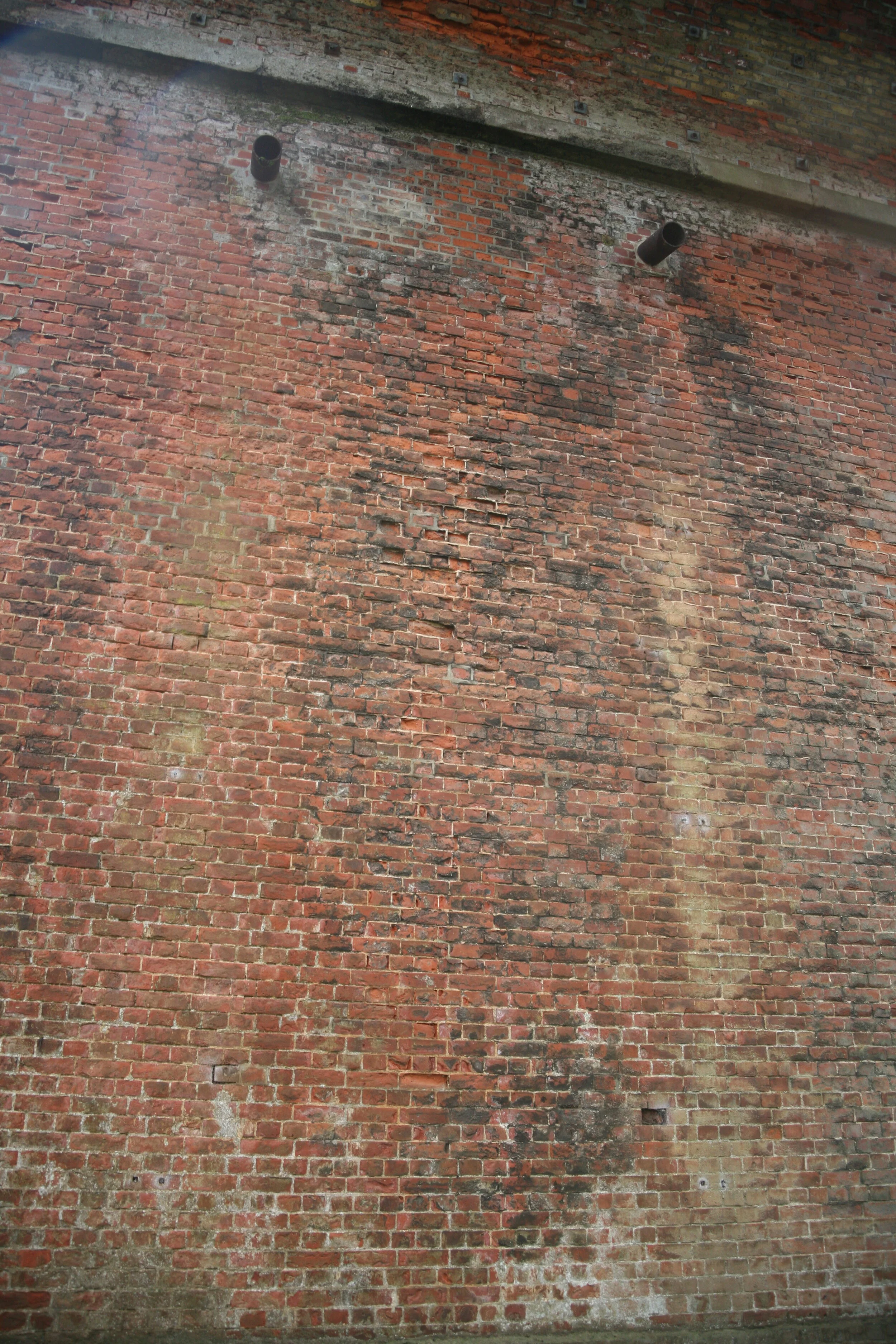
The drainage is interesting as can be seen in this elevation of the pier. Note that there are three drainpipes near the base and three directly above near the top of the pier. The original drains were 9 inch square chimneys down through the pier and out above ground level, These seem to have become blocked at some stage and bypassed by drilling a diversion in near the pier top.

The resulting weathering from windblown spatter was a sight to be seen.
Though there was plenty of weathering lower down too.

The eastern span provided some interest as well. It’s obviously smaller in that first picture. A closer look shows more interest.

We can see here that the pier was obviously built complete, then added to. Also, the span was reduced, actually from both sides, since the abutment has a false front on it too.


Looking closely at the top of the widened pier and comparing it with standard we can see that the springing has been moved three rings forward. What hadn’t occurred to me till now was that might have been done by cutting off the base of the centre. The right-hand arch definitely does not land vertically on the pier.

We measured the movement at the top of the pier using an A4 target of a set of rings. That was videoed as a train went through and a slightly larger set of rings superimposed on the video to generate an interference pattern. We used a domestic camera with a 40-times zoom. It was blowing a gale when we got to measuring and I had to tape the camera to a block of concrete with insulating tape to get it steady enough.
Getting the target up was fun too. I had a very delicate 10 m telescopic pole made from two 5-metre roller poles linked back to back. A paint roller on the top allowed it to be pushed up the face of the pier without bucking then bounced over the string course till the roller sat reasonably securely on top.
A pulley on the neck of the roller carried a light rope from which a very light aluminium frame was suspended to carry the target. The frame had three sharp screws projecting backwards, one at each edge of the pier and one some distance below the target.
A further rope was stretched back into the field beyond the pier and anchored with a ground screw, then pulled tight to clamp the spikes on to the pier.
Here is the rig in place, the photograph taken from the location of the video camera. The zoom was doubled with an extra lens and we were able to frame the A4 target exactly from this range.


Zooming in close lets us see how that worked. The rings only show as a grey disc because the resolution here is too low.
Once we had captured the video, we left the rig in place and retired to a local café where we processed it to obtain peak deflections left and right and confirmed that they were closely in scale with the effect of a rotating pier measured just above ground level. Only then did we take the rig down. The whole kit was packed up and carried from Exeter and back by train. At least £100k saved to be spent on a more needy case!
I never found time to dig deeply into what had happened to necessitate the reduction of the end span. It seems reasonable to assume that there was some sort of ground movement around that pier.
But I have come to wonder about a strange set of damage that appears in viaducts. Looking a little higher above this pier, there are lime runs and a drain indicating something about the level of the backing, though the top of the backing is surely above the topmost lime runs. If so, there is a line of patched brickwork much of the way across the pier at that level. Perhaps I need to go back when this lockdown is over.

After finishing this I found some images from the fringe tracking.
The first set of images is from the bottom target and the differences are very small indeed. It is most readily detected in the size and position of the slight dark part fringe at the left of the image.

The movement at the top of the pier is slightly more visible.

Notice particularly that the dark rings are almost exactly central in the bottom right, low and slightly left at top centre and high and slightly right bottom centre. It wasn’t possible to synchronise these measurements. The range of movement was about 0.3mm in the lower set and 0.6mm in the upper.
The scale of movement could be calculated directly from the fringes and did not depend on knowing the camera distance, though the distance was about 30 as shown below.
