
A PDF version is available here.
Something really out-of-the-ordinary this month. Rubira Bridge in Rwanda is the first masonry bridge built under the auspices of Bridges to Prosperity (B2P).

This is not by any means the first recent masonry bridge: B2P were inspired by the work led by Willem Van der Voort in Tanzania. 120 masonry bridges were built there with support of Belgian development agency Enabel between 2018 and 2024. With the principles and capacity established, the rural roads agency TARURA are now building more.
So Rubira Bridge is significant not just individually – though for the locals and for B2P it is certainly that – but also as the next stage in a steady building of momentum. The value of masonry bridges has been rediscovered, and bridges are being built again!
It is particularly pleasing to me that while, very sensibly, these bridges are built to design tables, some aspects of the design were checked with Archie-M, and I’ve had the pleasure of providing some training for both Tanzanian engineers and B2P.
If you are inspired by the work of Bridges to Prosperity, you can support their work with individual donations. Bridges to Prosperity also has many ways to partner with companies in the construction and engineering industry. Learn more about their corporate program and catch Nicola Turrini at Bridges 2025 in Coventry on March 12th. You can also reach out to him directly at nicolaturrini@bridgestoprosperity.org

Let’s have a look at how Rubira Bridge was built, using the weekly progress photographs from the project.
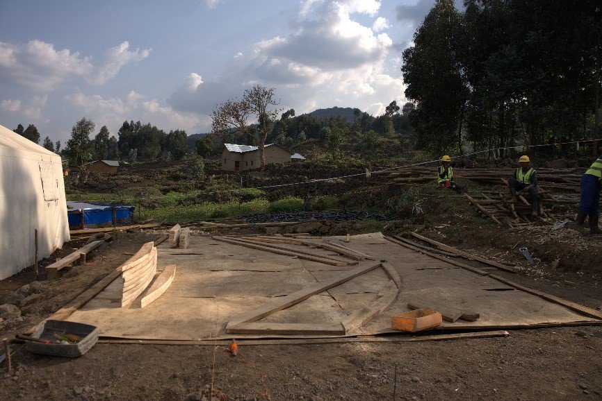
Rubira is founded on rock – a nice starting point as it removes the matters of bearing pressure and scour from consideration.
B2P now have bridges with soil foundations in design. Piles are not considered as they required specialist skills and equipment that are not readily available.

There is a concise construction manual to guide the whole process. It is a testament to the simplicity of the structural form that this runs to only 42 pages.
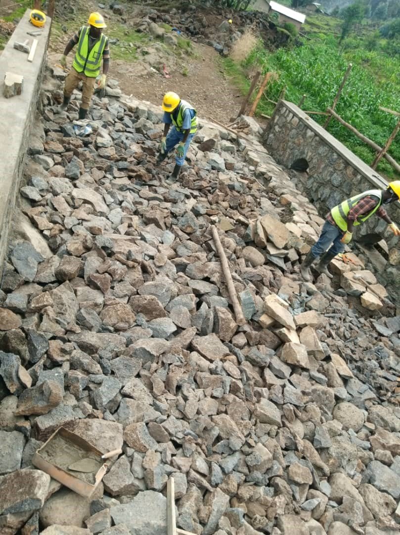
There was a lot of breaking out of rock here. Some pneumatic or electric tools are in evidence in some of the photos, it wasn’t entirely done with hand tools! But there is certainly a lot of heavy physical work going on here.

This is a photo from week 8 of 18, giving an idea of where the hard work goes. The design manual has a minimum abutment height – maybe it could be reduced when building on rock, but there is real value in having a set of rules that are safe with a minimum of custom design from a suitably qualified and experienced engineer. Especially when trying to scale up the numbers of bridges being built.
A good old level and a Very Long Staff being used to check the base of foundation level – the automatic level is one convenience our modern builders have that didn’t exist when masonry bridges were last being built in any number.

A supply of stone to be used in building. I’m excited for week 9!
There are strict rules about the stone: “For the construction of the stone arch bridge structure, large, high-quality stones must be used. … a. Stones should compose fine crystalline structure which should be free from cavities and cracks. b. Stones should be large, strong, and hard. c. The minimum strength of stone to be considered is 25 MPa”

Ok, week 9, now we start building back up. We start with a very deep hole, add some concrete mixed with rock (Cyclopean Concrete) to create a level surface, then the abutments come up.


Nice, big squared stones for the corners and faces, random rubble densely packed for the core. This is much more solid core construction that was typical in days of yore, with every void packed with cement mortar.
I would consider building back to the rock face in this case. It will be difficult to fill behind the abutment effectively.
Note below the ledge in the abutment.

Week 11, a big milestone: abutments finished. Filled behind with rubble, by the looks of it. The grid of logs over short stone columns creates a platform from which centring can be supported.

Work on the centring begins! The standard design for segmental arches involves a centre that sits on the abutment ledge, providing good support for the crown.
The centring is set out in the traditional manner, with string and a pencil on a flat surface.

Once the template is drawn on the ground, a set of matching centres can be made. These are of course reusable, as long as another bridge of the same geometry is needed nearby enough that moving them is less work than making a new set.

A pretty joint.

The centres are now set up between the abutments.

And propped and braced. Notice the masonry columns supporting the timber grid we saw before.

A nice detail of the centres sitting on the abutment ledge, with reinforced joints.

Lagging goes on the centres. Notice this is close packed. There is a note in the protocol about ensuring there are no gaps to minimise loss of mortar. At Rubira, a plastic sheet was even laid on top of the timber.
It is frequently possible in old masonry bridges to see the size of the boards used in construction, because the joints that line up with the gaps between boards are short of mortar.

Cute baby centres! These are to form openings at the base of the parapets – I assumed for drainage in extreme conditions, but I understand now these are purely aesthetic. There are smaller, slightly lower spouts for water drainage.
That takes us to the end of week 13.

In week 14 we start turning the arch. Squarish rubble, only the edge stones are dressed.
Note the bed of mortar beneath the stones, this feature surprised me. It provides a bed for the stones to sit on during construction, but leaves no stone visible on the soffit.

Due care being taken that the stones stay radial.

Here we see the “keystone” being inserted. The significance of the keystone to an arch is often exaggerated – no voussoir is more significant than any other – but it is important in the construction process. Driving in a wedge-shaped stone will start the process of load transfer from centring to arch compression.
A later photograph shows the keystone course bedded in mortar, so this photo presumably shows the stone being offered up to check the size.

A layer of mortar over the centre in the bottom of the slot awaiting the final stones.
The arch is complete!
But – and this is vitally important – the centring is not yet ready to be struck. Backing – solid masonry over the abutment behind the arch is still to be added.
It was once part of the bridge-building mason’s received knowledge that an arch cannot be assumed stable until some minimum level of masonry backing has been added. In fact this is unlikely to be an issue with the Rubira geometry (the problem is most acute with arches that turn vertical at the springings), but in a table-based design process, just as with rule-of-thumb based designs of old, a universal safe rule is needed.


It is worth having a quick look at this in Archie-M: look ahead to the next photograph if you’re not interested in the engineering. A 6m span semi-circular arch to the Enabel design manual must have a ring thickness of 400mm at the crown. If the arch is built to 400mm thickness and the centring removed, with no backing and no fill, the thrust looks like this. Note that we’re making use of a new feature in Archie-M 2.7 that makes it easy to model bridges with fill removed, whether fully or partially.

Also new is the ability to dynamically modify key dimensions. Left, we see the effect of reducing ring thickness millimetre by millimetre until the thrust just touches the extrados at the springings. The purple lines show clearly where the thrust escapes the masonry. A thickness of about 350mm is on the brink of collapse.

It doesn’t take much extra weight on the crown – say if the stones used at the springings were slightly thinner, those at the crown slightly thicker – to reach instability without reducing the ring thickness. So without backing, the arch here is a bit too close to unstable.
Also new in Archie-M 2.7 – piecewise linear road surfaces. Here the road surface is at springing level except over the central 1.2m. Anywhere the road surface is below masonry level, the masonry level is taken. That will make it simple to model asymmetric excavations, for example.

The Rubira geometry is 6m span, 1.2m rise, 440mm ring thickness at the crown. This is much more stable as a bare arch – notice that the thrust touches the intrados at the springings (where the arch meets the abutments).

If we add the same road surface as above, which here adds much greater load at the crown, we see that although the outer hinges (the points where the thrust touches the intrados, marked by circles) move slightly away from the springings, the line of thrust is still thin and there are still only three hinges, so no mechanism and no failure.

Another new Archie-M 2.7 feature is visible in these screenshots: stress indicators at each cross section. These show the stress distribution implied by the thrust, assuming uniform material properties and no tension. That should help if you’re familiar with engineering statics but not thrust.
Here we add the backing and fill, and find that (as we would expect) Rubira Bridge could carry standard UK road traffic with aplomb.
I’m now miles off piste. Where were we …

… Ah yes, we were in week 16, and around the same time as the keystones were being driven in, masonry backing was being added …

… bringing the masonry up to a nice level with the centring still firmly in place.
Masonry here looks to be above crown intrados level, which was a common level used in railway era bridges.

Moving into the penultimate week, the parapets have gone on with their decorative arches.
One detail here I would expect to cause a bit of a maintenance headache. The rear face of the abutment has been brought right up to road level.
There is some “fill” in the form of rubble without mortar, then a final layer of stone in cement mortar to provide the wearing surface.

The space behind that hard abutment corner is part filled with rubble …

Then topped off with soil. This is where I anticipate difficulty – the hard edge just under the soil will make its presence felt. It also seems to create a difficult slope for wheeled vehicles.

Some care going into finish here.
If you look closely at the wing wall in the foreground you will see it is peppered with drainage holes.

I wonder how long mortar layer on the soffit will last, but the capacity of the bridge will not be harmed if it cracks up.

The drains in action – lucky / good planning that the foundations were finished before the rain arrived.
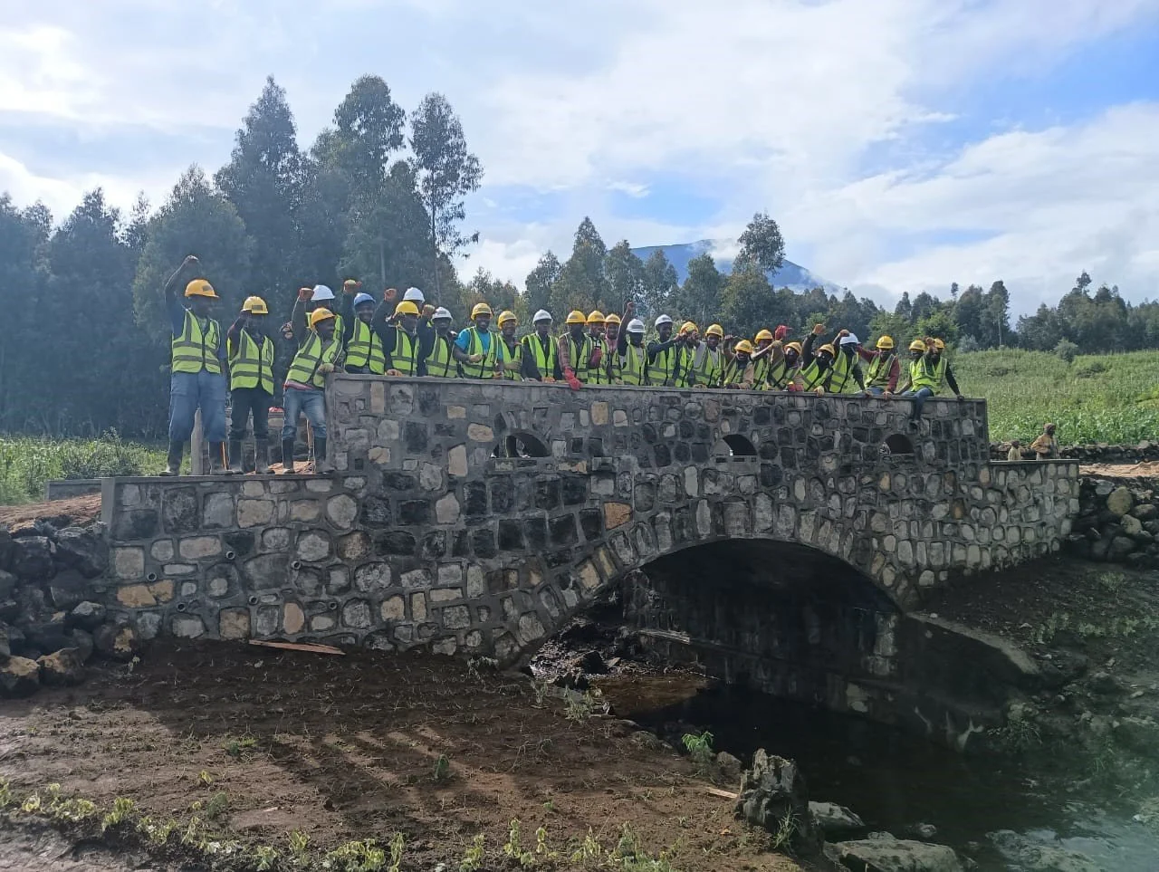
And that’s a bridge! Time for a well-deserved celebration.
18 weeks to build a bridge that will provide value for decades to come – perhaps even, like the many masonry bridges we depend on every day in the UK, for hundreds of years, built entirely with local labour and largely with locally sourced material.
The exception to that is perhaps the cement. There is interest from some in switching from cement to lime mortar, thereby replacing another industrial product with a material that can be more locally sourced and manufactured. One problem with that may be available skills.
As is, with so much masonry with joints carefully filled with cement mortar, this is likely to be a very stiff bridge. Indeed it would be very interesting to measure deflections, though you might wait a long time for a sufficiently heavy load to register!
I’m even more excited now than I was when I sat down to write this. I wish both Tanzania and Rwanda every success with their new bridges, and hope to hear of wider adoption. And I look forward to helping where I can.

Remember there are links back up near the top if you’re interested in supporting Bridges to Prosperity.