A PDF version is available here.
A family walk-cum-bridge-hunting jaunt out west took us by chance through Pontrhydyfen, in the Afan valley north of Port Talbot. The original pont must have been lost, the road now crosses the Afan on a nondescript concrete number, but the village is home to two fine masonry structures. Pontrhydyfen Viaduct now carries the Richard Burton Trail, and didn’t interrupt our homeward journey; Forgotten Relics has a summary of the history of that one.
The aqueduct inspired an unplanned, albeit brief, stop. It strides across the valley with four unusually long spans, much longer than typical for railway viaducts, and the shape is intriguing. Here is the view as we came down the hill.
The bridge was built in 1827 to carry water to the Oakwood Ironworks. That makes it contemporary with early railway viaducts but before the boom. It was converted to carry a railway in 1841, and abandoned in 1874. Now scheduled and grade II* listed, it serves as part of the national cycle network, not only saving cyclists from tangling with the faster traffic running below, but also saving a stiff climb up the valley side.
The views from below are dramatic. The view left shows how slender the superstructure is in plan. Notice the lime staining from the rubble ring continuing down the pier, where the dressed edge voussoirs are clean.
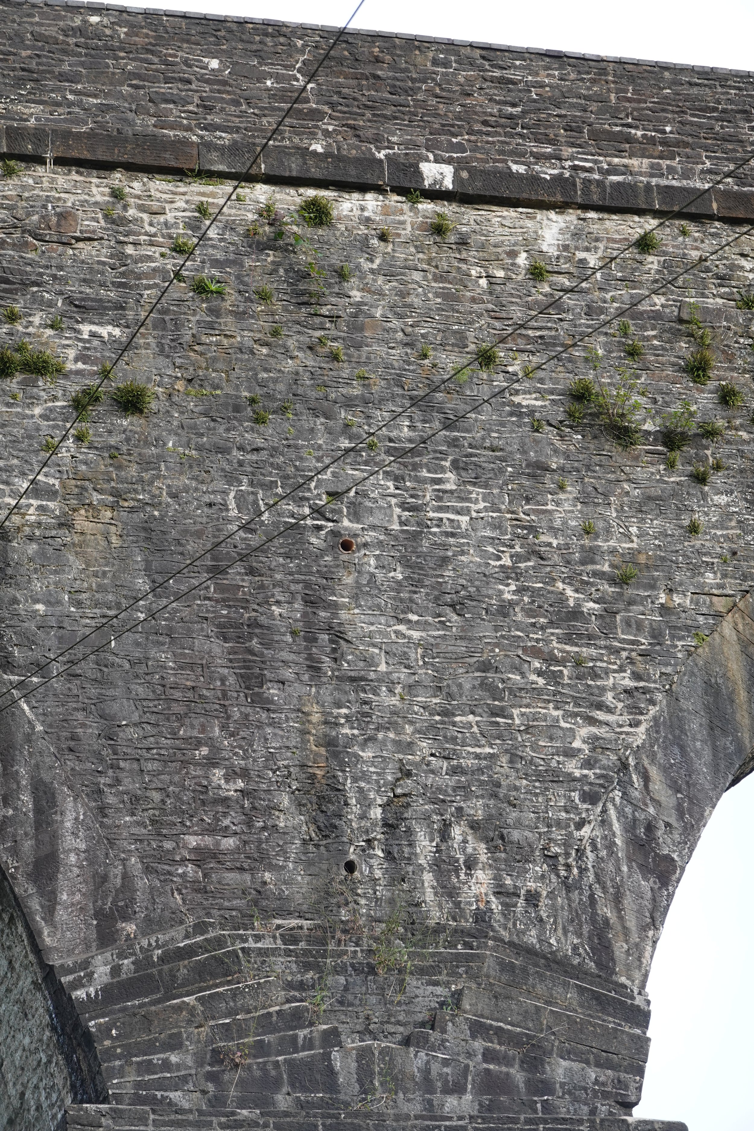
Zooming in on the area around the springing (right) we can see that the ring and spandrel wall corbel out in steps, but the soffit comes to an abrupt ledge.
Zooming in a bit closer still (left - the Sony RX100 I inherited from Bill is a phenomenal tool), it looks distinctly as if the rubble of the ring extends out further as the outer voussoirs step out. The face of at least one lower voussoir has spalled off, perhaps as the less rubble masonry has compressed slightly relative to the stiffer ashlar. The corner of the pier seems to be having some trouble too, what is driving that?
There is a big volume of spandrel here. Two clay drain pipes emerge (right), but I suspect these are retrofitted. Comparing piers this is confirmed by the vertical position varying.
Left, the clay pipes haven’t broken off, and we get a better view of the corbel on the elevation and the makeup of the ring. The fight between ashlar and squared rubble is visible again.
I left struck by the scale of the arches, but the shape was also unusual. Clearly not segmental, the curve is presumably either elliptical or multi-centred. In training courses I point out that the eye is remarkably sensitive to the abrupt changes of curvature of three-centred geometry. The rarer cases with five or more centres have subtler changes and will be less obvious, but we can generally see the difference between a three-centred curve and the continuous change of an elliptical curve.
Looking around the quarter points in the first view above, my first guess was that the curve is three-centred (see right). Unusually though for either multi-centred or elliptical geometry, it doesn’t seem to come to vertical at the springings. That is common in large span Norwegian masonry bridges, springing from rock, but I haven’t come across it before in the UK (examples please if you have!). The possibility that the piers were originally more slender and later enlarged burying the true springings was discounted because the decorative corbel is clearly original. Perhaps the impression is an artefact of the corbel. Can we confirm that?
I didn’t have anything with me to take measurements, and the springings are obscured from the ground in any case by the step at the pier top. The photo at the start of this piece is squarest view I have, so the best we can do is to overlay trial geometry on the photo and see what sort of fit we get.
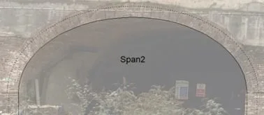
I have taken to using PowerPoint for this. There are surely better tools, but nearly everyone has ppt or something similar to hand. If we make a blank slide, crop the photo to the arch, and size the cropped area to make the most of the page, we can then paste screenshots from Archie-M over the top with partial transparency, and juggle the size and position to compare the two.
The common case in assessment is that we have a measured span and rise and we can see the springing points. In this case, if we have a photo from close to mid span and now too far below the level of the arch, it is very quick to check whether the shape is elliptical or not, or at least whether the difference is enough to matter. Here’s an example. The ring thickness in this was set to 4 bricks rather than the 5 visible in this wire-saw-cut elevation, but the shape is a good fit.
For our current case, the photo is not from mid span, we can’t see the springings, we aren’t sure if they are vertical or not, and we have no dimensions. How far can we get?
We don’t have a span, so let’s use 10000mm (the actual span may be closer to 20m, but the ratios are easier if we use 10m). The span to rise ratio is clearly less than 2 (that would be a semicircle in any geometry) and more than 4, so let’s try 3, so rise 3333mm. We test an elliptical curve first, as the quarter point rise is fixed by the span and rise, so there are fewer variables.
That’s an interesting result. The Archie-M curve drops below the real intrados to the right, but it’s much closer at the left. I guess that is a result of perspective distortion in the image. Compare the ring thickness drawn by Archie-M with actual ring in the photo. The Archie-M ring thickness is too large everywhere, but it is better at the right than at the left. Again, the difference is perspective.
(If you use Archie-M, the trick to getting a clean picture of the geometry without a thrust line is to open the bridge wizard at the arch geometry page, and click next. Clicking back, editing, and clicking and next allows you to test different geometries quickly. This will be slightly easier in 2.7, as changes to inputs update the view immediately.)
It looks as if we aren’t going to get very far without correcting perspective a bit. Affinity Photo has a tool to do that. All of the distortion we’re interested in is in one plane, so single point perspective should do it. We’re a bit limited in control points, but the string course above and the top corners of the corbels below we might assume are both level. No doubt there is a foreshortening vertically as well as the camera is well below springing level, but we don’t have any vertical lines to work with.
Left is a rather hasty tweak, with the grid lines aligned with the top of parapet and top of corbels (everything below that being hidden by vegetation to the left). Right, the result. The string course still isn’t dead level, but it’s closer.
While we’re looking at that string course, my eye sees a dip to mid span. Is that real? Overlaying a straight edge says it is, but in relative terms it is slight. On this large span it might not be trivial.
Trying our overlay again with the corrected image, we find that the aspect ratio doesn’t fit any more. The springings in the screenshot are clearly too high.
Thinking about it, my perspective correction will have stretched the image vertically everywhere except the very right hand edge, with no corresponding stretch in the width. That is unavoidable I think, which makes extracting a span:rise ratio impossible.
Accepting the vertical stretching, we can stretch the Archie-M image too. We finish up with a close but not perfect fit around the intrados curve, and springings not far from top of pier ledge.
From which, we have a revised though partial view on the geometry. The span:rise ratio might well be 3:1, but we can’t be sure without measurements or a square on photo.
I’m still unsure about the shape – from this, elliptical is possible. The deviations we see in that last overlay might be saying that it is three-centred, but we’ve finished up with too many variables to be sure.
One thing seems clear though. The true springing is probably at the pier top ledge – the feeling that it is lower must be an optical illusion, probably created by the corbels.
Ah well, on the list for a return visit with some measuring equipment at some point, but I can put the idea that it is an outlier in terms of having non-vertical springings to bed.
Even in that last image, the real ring is smaller than that in the Archie-M model, where I have a 400mm ring on a 10000mm span. If we suppose a real span of around 20m, that means a ring of perhaps 700mm. Rankine’s rule of thumb (sqrt(0.12*span in ft)) would ask for at least 850mm, so the feeling that the expressed ring is slender is fair. Whether the squared rubble between is thicker or thinner we don’t know.
The conversion to rail is interesting. An aqueduct will never experience any concentrated load. You would want to show at least a little backing (stiff masonry over the pier between the arches) to pass this for any interesting rail loads to modern practice. Passive pressure can get us to RA10 without impact, but only RA3 with impact.
It clearly survived its stint carrying mid-19th century loads. A train of wagons carrying input or output for an iron or copper works would be the heaviest loads of the day, but with close spaced axles the load would be well distributed. Arches suffer under concentrated or eccentric loading. The most adverse condition here will have been from the leading and trailing ends of the trains.
The geometry is quite different from most rail viaducts of the time, so my last thought is whether anyone felt any concern about the repurposing. Or whether the effect of live load on arch stability was really off the radar.


