A PDF version is available here.
Of all organisations, Highways England have been lumbered with the “care” of the Historic Railways Estate. Oh, but the name has been changed again, National Highways it seems. I am reminded of this:
I wonder how many millions was spent on rebranding and how much paper has gone to recycling as a result.
I was alerted to this via the HREgroup on Twitter where they are @theHREgroup. We have models of a couple of the bridges that are being fought over. So far, this is the one in worst condition. There are many bridges on live rail, in worse condition than this carrying freight trains so it is a very bad thing nationally if money is being diverted away from them.
It is, of course, very easy to blame the engineers for this but I feel sure it is the long arm of politics. The government said to HE/NH find a way to get these off our back. HE/NH said to their consultants, find a way to remove all risk from these bridges. Few (modern, cash driven) engineering companies would resist such a demand. The trouble is that we don’t understand how and why these bridges deteriorate and so have no real idea what makes them safe. There will be more comment when we have looked.
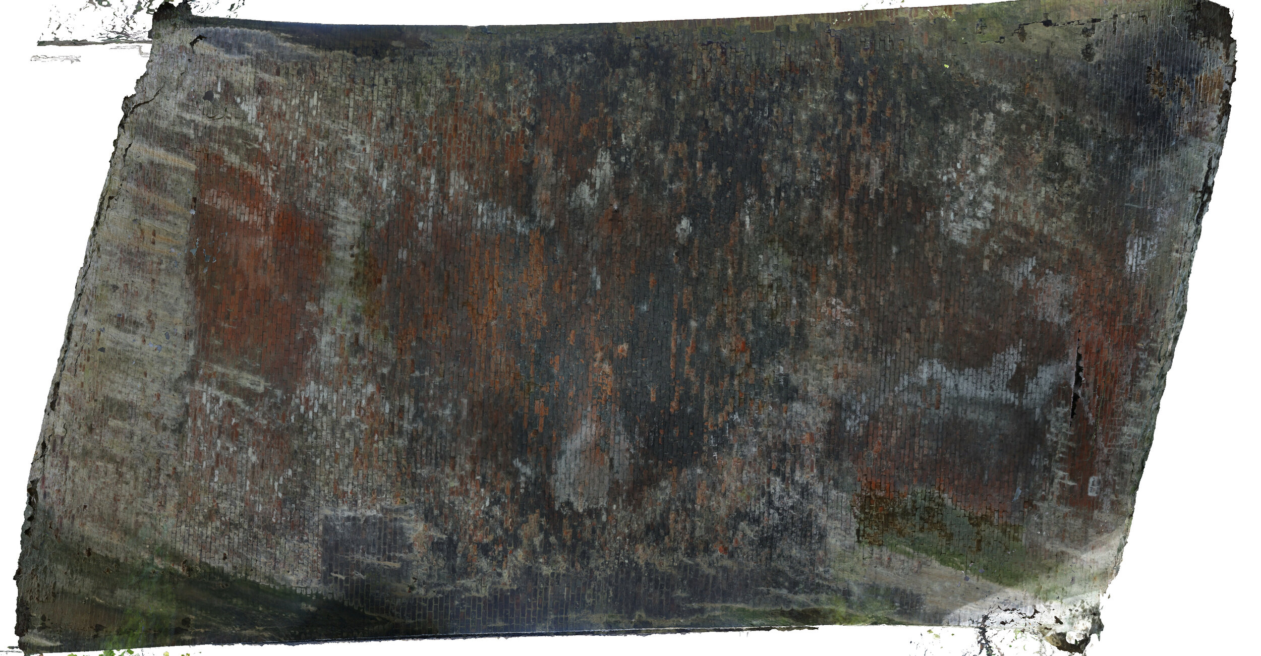
The bridge is here on Google maps. Our model was produced by Mohamed Troudi, a gap year student who got a pretty raw deal working with me for a year when first I broke my hand then I started falling over, then I was diagnosed with cancer. He went to the site with a camera and a long pole and photographed as best he could. The cover of the soffit is good but the spandrel walls are patch because of heavy vegetation and their extreme height. But here is an elevation.
The white patches are bits that don’t appear in any photographs.
You can view the model on Sketchfab and for once, this model is pretty nearly as good as the highest quality one.
The first thing to notice here is that patch of broken bricks at the third point.
Let’s look at the soffit, though, because that tells us a lot.
The bridge is skew! You can see the lime runs following the steepest slope. Even at this scale, there looks to be damage top right and bottom left in the acute corners.
There was no way to survey the model so levels and scale are just a guess but I could put a plane on the bottom of the two string courses and it reasonable to assume that is horizontal. Dragging that down on to the arch shows the springing pretty much level. The faint white lines at each end are straight and parallel.
Lifting the plane to cut the arch shows some distortion.
These lines are contours so here we have the top edge lower than the bottom and the left hand line has a king which means a crack. Perhaps there is one to the right too.
Note the solid lime band above the left hand springing then a gap and another line of lime runs. For straight lines like that there has to be something in the construction and it seems likely that there is solid backing below the lower line and hollow between that and the upper.
Looking square on shows that pattern.
There is a lot of mortar erosion in the clean band and that is often caused by hollows behind which enable the arch to change temperature more rapidly.
Strangely, the other end of the span doesn’t show this banding. What this image does show, though is rubble stone below the springing. I suspect that is rough and ready foundation construction (perfectly adequate as such) which was intended to be buried and probably was originally.
Looking closely at the corners, the damage is much more apparent.
Here is the acute corner at the unbanded end.
That crack has formed as a result of shear between the arch and the spandrel wall. There has been regular movement over a sustained period to create a crack of that width. To the left of this in the obtuse corner there is no such crack.
The obtuse corner at the banded end. Shows no crack.
At the banded end there has been a lot of patching, but the crack has just come though. Papering over the cracks is NOT a cure. It’s a temporary disguise.
There is undoubtedly some cracking at the obtuse corner here.
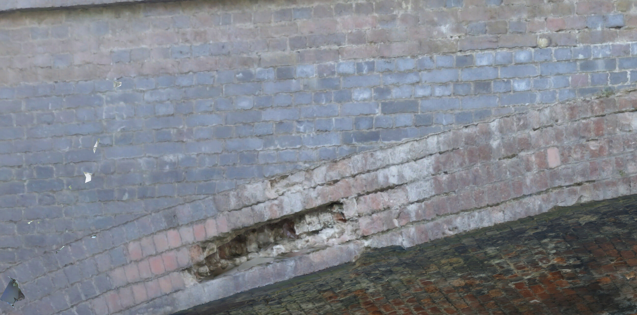
If we look a little closer at the crushed bricks on the edge of the arch at the third point, we can see they are surrounded by patching. This suggests that the damage was not in this location when the hard brick patches were installed. I hope we have learnt a little since those days about not using hard bricks to patch into soft brick structures. It is the same issue as not using hard mortar and soft bricks.
We can look closer yet and see the nature of the damage better.
I would expect to see either or both of a horizontal or vertical crack in the spandrel leading to this crushing point. Perhaps there is one just above. There is certainly a small crack tracking round the outside of the arch.
Following round the arch there is interesting damage at the crown too.
With a proper forensic investigation, this bridge has a great deal to tell us about the existing bridge stock and how it might behave. A few thousand pounds (less than £10k certainly) spent on having a thinking engineer examine this and photograph it with more care would repay handsomely in fresh knowledge and understanding. I really can’t, though, afford to do it at my own expense. I would dearly love to do some measurement of movement here because this is damage I have only seen in viaducts before.
If this bridge is infilled it will not stop the movement. The cracks will continue to grow. In my view, the most likely outcome is a spandrel falling off but with fill in place there will be no way to anticipate that. The law of unintended consequences!
And just before I shut down, following the BoM 126 Cannington, a kind follower forwarded me this picture from a book he had bought. It shows the scale of the slip which is now completely hidden in tree growth.


