
I have been putting together notes on bridge building for a book but over the past few weeks I came across some stuff that is worthy of gathering here, I think. Some of this is stuff I should have known for years (not least because I have had the photographs) but I am sure we can all be “slow learners”!
A PDF version is available here.
So, where do we start? The first thing I want to labour is the basic nature of bulk masonry, which is that there is no such thing. Indeed there never has been. If you look closely at the pyramids you will see that the internal blocks are not tight fitting.
This bridge at Aesepus (photo courtesy of Galina Fingarova) is often claimed to be Roman, though closer examination shows it to have been reconstructed. These internal spandrel walls, though, are very rough and ready compared with the skin.
By the 18th century, French engineers, led by Jean-Rodolphe Perronet, were building arches of tight-fitting stone but the rest of the masonry was definitely skin and core, as shown here.

This drawing by Smeaton, from the same period, shows similar work but cut in a different direction:

Here, the skewbacks are sitting on firm walls and there is a very obvious band of fitted stone transmitting the horizontal thrust from side to side. He must have known that the tight fit ensured that those stones carried the full load.
In the UK, John Rennie built fancy bridges and used tight-fitting stone throughout, but few other engineers did so. As seen here in his London Bridge being taken down.

And in this section of Waterloo Bridge.

This drawing is from Encyclopedia Britannica and in the right-hand half of the arch shows the thrust line calculated by Thomas Young.
That this rough core and tight shell form of construction was normal is perhaps illustrated by the care taken by G.W. Buck in his specification for the brickwork in Stockport Viaduct.

By “overhand” I am sure he means above about shoulder height. The bricks must be put down, not up, so that the bricklayer and supervisor can both see the work well bonded.
Contrast that with this cut through the abutment of Moco Farm Bridge in 2015.

Here, only in the skin are the perpend joints properly full of mortar and the bricks are laid in straight lines (more or less) in both directions. No sign of bond at all.
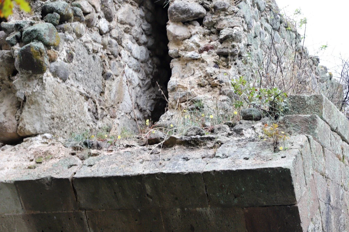
Where work was difficult, for example in a narrow gap on top of a pier when an arch is first started, the bricklayers would be faced with particular difficulties and might deal with them as best they could. Only when the work is cut off will anyone discover, as here at the former Liverpool Road station in Manchester. This section is visible to anyone who visits the museum there.

Here, the arch ring is clearly intended to be bonded through in two full brick rings. The outer ring stops short about eight courses up and the first two courses are hardly tidy. The lowest four courses of the inner ring are not much more than brick slips against the centre with rough fill behind and the and the next five are roughly laid and badly filled with the header courses replaced by disguising snap headers. The stresses are modest and the masonry solid enough to sustain them but determining the force flow through here is impossible.